
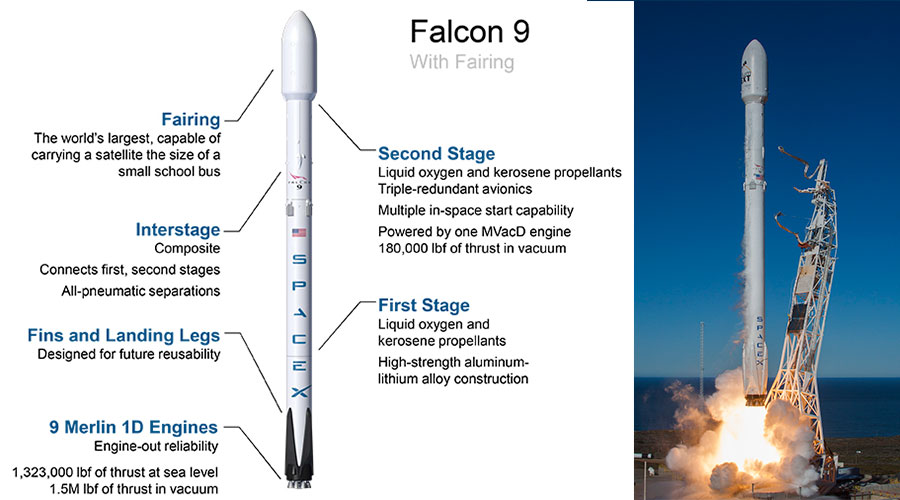
Falcon 9 is a two-stage rocket designed and manufactured by SpaceX for the reliable and safe transport of spacecraft into orbit. Falcon 9 was designed from the ground up for maximum efficiency and reliability. Falcon 9’s simple two-stage configuration minimizes the number of separation events – and with nine first-stage engines, it can safely complete its mission even in the event of an engine shutdown.
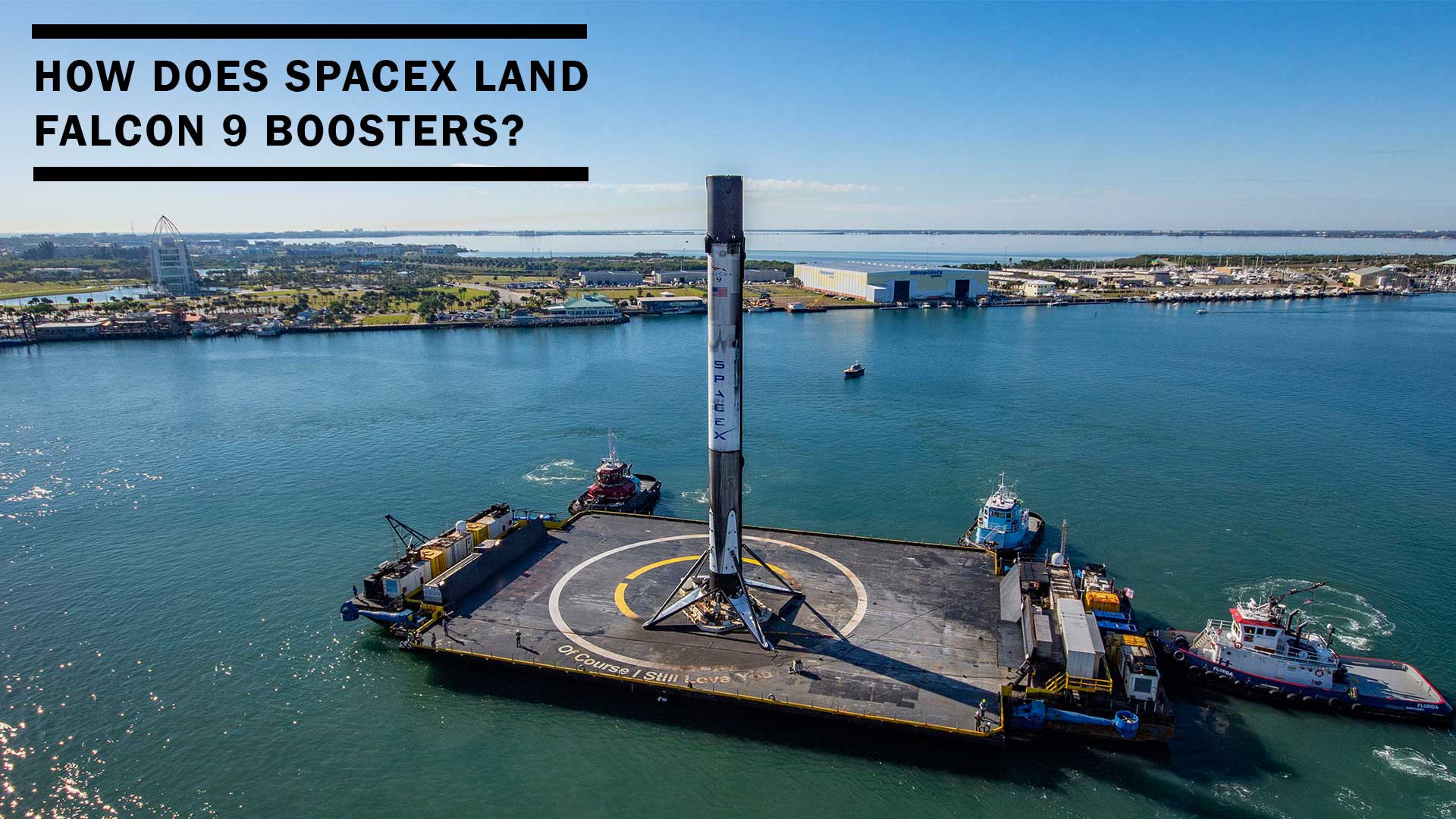
Falcon 9 is the first orbital class rocket capable of reflight, achieving the first fully automated landing from space on December 21, 2015. SpaceX believes rocket reusability is the key breakthrough needed to reduce the cost of access to space. In September 2011, SpaceX publicly announced its reusable launch system development program. The company began flight tests with the suborbital Grasshoper rocket and continued with F9R-Dev until 2014. Those tests were crucial to learn from failures and improve the design and systems of the Falcon 9. Bringing a rocket from space back to Earth to be flown again is an incredibly challenging engineering task. After deploying the payload into orbit, the rocket undergoes hypersonic velocities, and extreme vibrations and temperatures due to reentry into Earth’s atmosphere. Not enough, the slender shape of the craft makes it really hard to stabilize and control the orientation and trajectory while descending at high speeds.
As of April 22 2020, Falcon 9’s first-stage boosters have been recovered in 51 of 61 landing attempts (84%), with 27 out of 31 for the latest version, Block 5. How could SpaceX reach this success rate? What technology and devices do they use to achieve the unachievable?
After acquiring valuable experience and feedback from numerous tests, the team of SpaceX’s world-class engineers came up with the solution to the landing problem. Falcon 9 team developed five major components that make Falcon 9’s first-stage recovery possible: re-ignitable and orientable rocket engines, cold gas thrusters, hypersonic grid fins, landing legs and robust software algorithms for precision landing.
Smart autonomous craft: What are the systems that make recovery possible?
Merlin 1D (M1D) rocket engines
The Merlin 1D (M1D) thrusters are the last iteration of SpaceX’s in-house developed Merlin family engines that power the Falcon 9. Burning liquid oxygen LOX and rocket-grade kerosene (RP-1) propellant, nine M1D engines power the Falcon 9 first stage with up to 854 kN (190,000 lbf) thrust per engine at sea level, for a total thrust of 7,686 kN (1.71 million lbf) at liftoff. The first-stage engines are configured in a circular pattern (Octaweb), with eight engines surrounding a center engine.
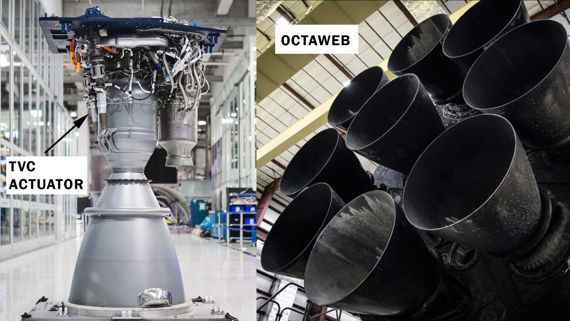
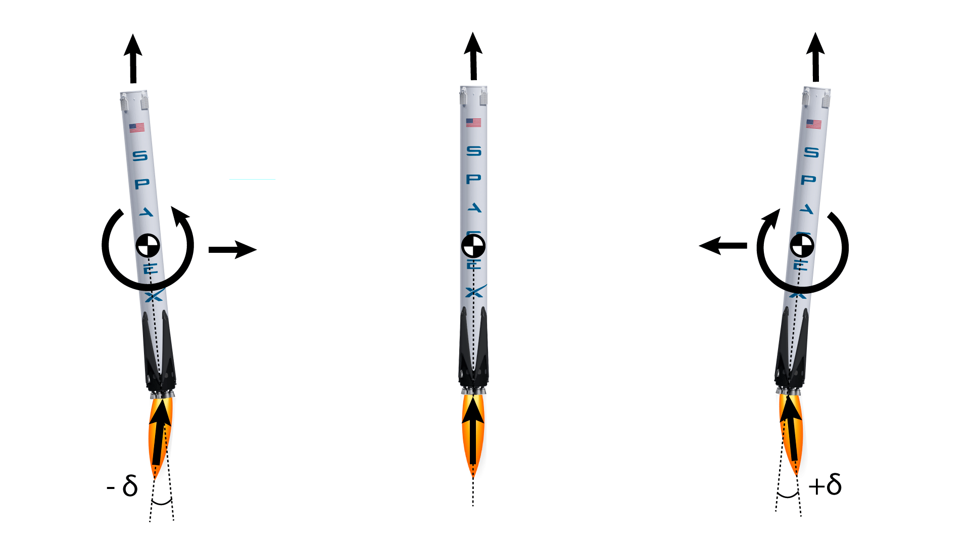
The key feature of fist-stage engines is re-ignition when starting the descend stage, consuming the remaining fuel to land the structure. Falcon 9 can sustain up to two engine shutdowns during flight and still successfully complete its mission. Each of the M1D engines can be gimballed on a single axis thanks to the thrust vector control (TVC) system, thus allowing the rocket to control the direction of thrust. The TVC pulls from the high-pressure kerosene system, rather than using a separate hydraulic fluid and pressurization system. Owing to the Octaweb arrangement, the engines can be gimballed to control pitch, roll and yaw. Thus, Falcon 9’s TVC allows for both attitude and trajectory control.
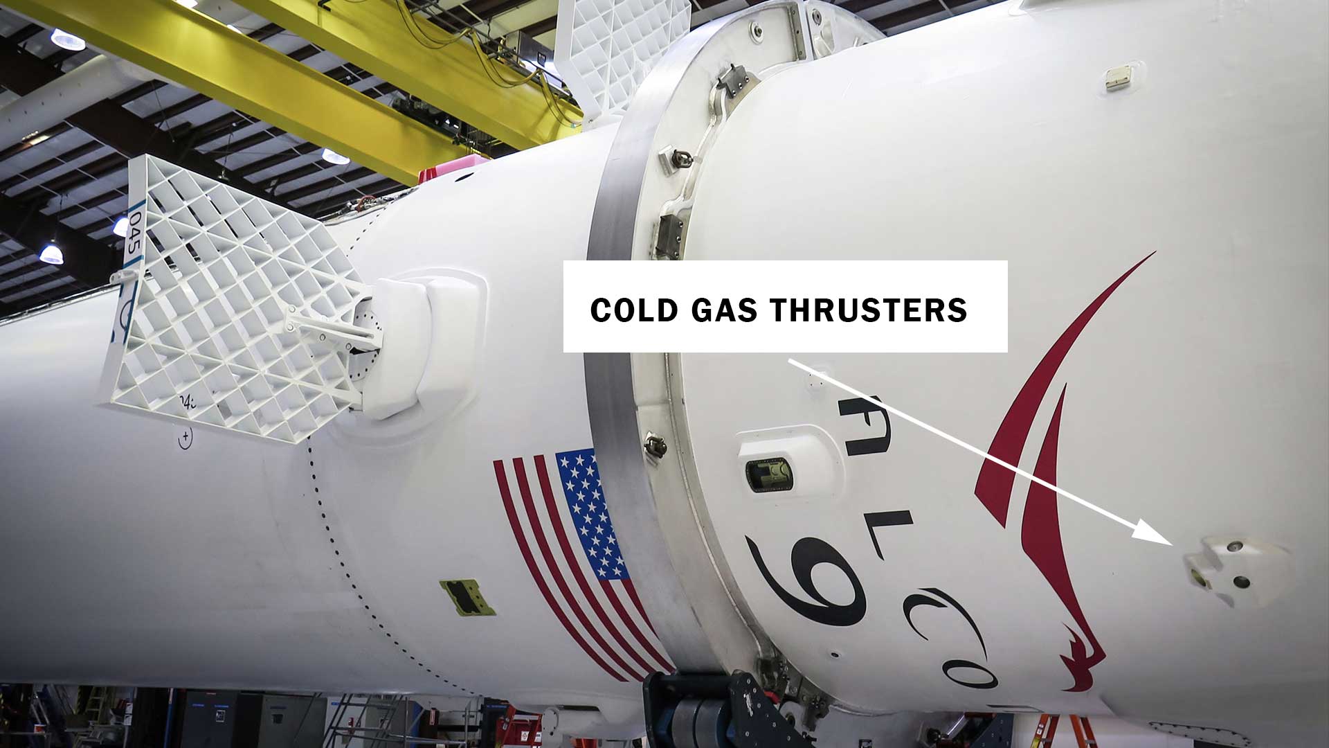
Cold gas thrusters (GN2)
At the top of the first stage of the Falcon 9 rocket there are two pods of cold nitrogen gas thrusters (GN2). Each pad contains a cluster of 4 nozzles aimed at aft, left and right, and outboard. These 8 thrusters use the expansion of highly pressurized nitrogen to generate thrust and re-orient the first-stage booster during the descent phase. Owing to their location and orientation cold gas thrusters can control pitch, roll and yaw. The GN2 is more reliable and produces less contamination than a propellant-based reaction control system.
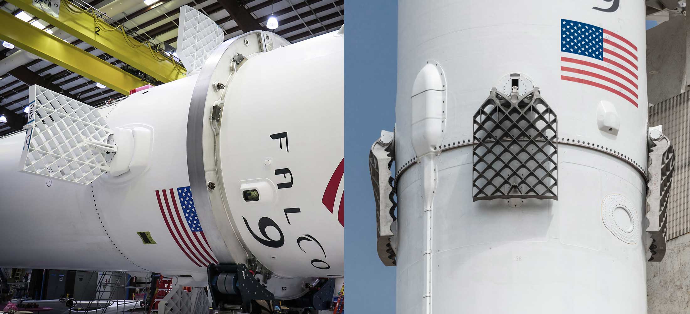
Grid fins
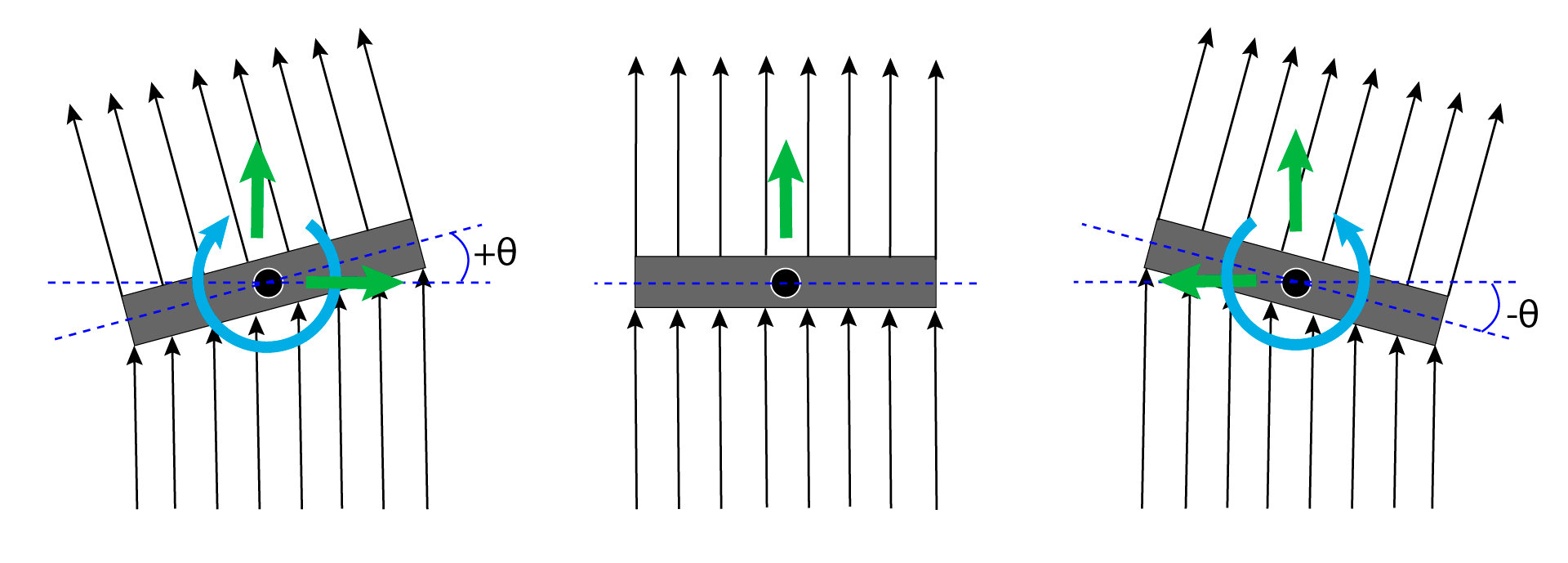
Falcon 9 is equipped with small, foldable heat-resistant hypersonic grid fins needed for steering the first-stage as it plummets from the edge of space through Earth’s atmosphere. The fins are placed in an X-wing configuration and are stowed on ascent and deployed during reentry. The fins, which measure 4 feet by 5 feet, are steerable control surfaces that allow pitch, yaw and roll control by means of aerodynamic lift in order to target a precision landing. As the booster reenter Earth’s atmosphere, the air passes through the grid structure at hypersonic speed. By steering the fins, the air flow is deflected generating the aerodynamic force needed to control the trajectory and attitude of the first stage. As opposed to conventional planar fins, grid fins have notorious advantages for entry, descent, and landing operations, specially at hypersonic velocities.
Some of the features that make grid fins suitable for Falcon 9’s descent are outlined below:
-
High aerodynamic effectiveness for a range of Mach numbers. During re-entry, the grid fins develop shock waves due to hypersonic velocity. Grid fins are optimally designed for hypersonic regimes and allow precise control even in the presence of shocks. At subsonic speeds, the drag and control effectiveness of the grid fin are almost similar to a conventional fin. Grid fins offer weak stability at transonic regimes because of the formation of bow shocks reduce the airflow through the grid cells and increase wave drag. However, transonic speeds only last few seconds during the descent phase.
-
Small hinge moments with minimal shift of the center of pressure. Due to the short chord, the aerodynamic center of pressure is closer to the fuselage of the booster, inducing smaller hinge moments. Low aerodynamic moments require less torque from the control actuators to rotate the fins, which leads to an increase of deflection angles—and thus, controllability—and a reduction in size, weight, and complexity of the servomechanism.
-
Compact size and possibility to be folded down to the fuselage. During ascent, fins are folded, inducing very little drag on the vehicle and optimizing its efficiency. Once the payload is deployed and the descent stage initiated, the fins are unfolded to stabilize the booster on its return to Earth.
Landing legs
Falcon 9’s first-stage carries landing legs which deploy few seconds before touchdown and allow for the rocket’s soft landing. The four legs are made of state-of-the-art carbon fiber with aluminum honeycomb. Placed symmetrically around the base of the rocket, they stow along the side of the vehicle during liftoff and later extend outward and down for landing. Deployment is accomplished by a pneumatic system using high-pressure helium. The total span of the four is approximately 18 meters (60 ft), and weigh less than 2,100 kilograms (4,600 lb).
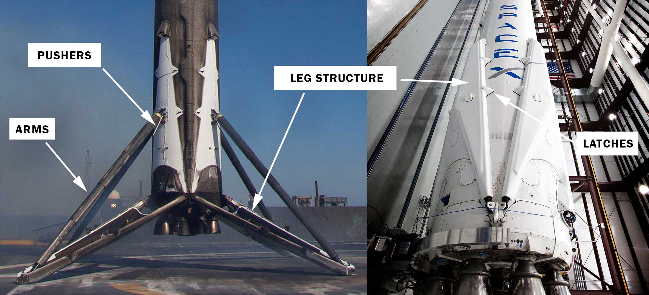
There are four major components on the Falcon 9 landing legs:
1) Leg structure
The legs are the triangular structures made of carbon fiber with aluminum honeycomb that provide the booster with rigidity and stability to remain in place once landed. They are aerodynamically designed to reduce drag when they are stowed during the ascent stage.
2) Deployment arms
The deployment arms are cylindrical, telescopic struts that attach the tip of the leg structure to the first-stage fuselage. A pneumatic mechanism gradually extends the arms using pressurized helium. When fully extended, they lock the leg in place. This system also acts as shock absorber when the booster hits the ground.
3) Pushers
The pushers are smaller extendable arms that are attached to the base of the attachment joints of the main arms. The legs are lowered by gravity and the main telescopic arms slow down the downward motion of the legs so they won’t collapse immediately upon landing. The purpose of the pusher is to kick the legs slightly outward from the fuselage, enough so that gravity begin to pull the legs down.
4) Latches
Latches are small triangle-shaped pieces that fasten the landing legs to the fuselage to prevent the legs from accidentally deploy during ascent or at any inconveient time during the flight. During leg deployment, the latches disengage allowing the pushers to kick the legs out of the fuselage.
Flight software and sensors
Bringing a craft from space back to specific targets on Earth would not be possible without robust flight software algorithms and a sensor suite for precision guidance, navigation and control. Falcon avionics feature a flight-proven, three-string, fault-tolerant architecture that has been designed to human-rating requirements. Avionics include flight computers, Global Positioning System (GPS) receivers, inertial measurement units (IMU), SpaceX-designed and manufactured controllers for vehicle control (propulsion, valve, pressurization, separation and payload interfaces), a network backbone, S-band transmitters and a C-band transponder for range safety tracking.
The inertial measurement units comprise a suite of accelerometer and gyroscope sensors that measure acceleration and angular rates for trajectory and attitude determination. The GPS sensor improves the navigation state of the vehicle for accurate tracking. This information is feeded into onboard filters and control algorithms that send signals to actuators for thrust (cold gas thrusters and Merlin engines) and aerodynamic control (grid fins).
From space to Earth: What is the flight procedure to land the booster?
After second-stage separation, the first-stage switches to recovery mode to safely return to the landing site. In recovery mode, the first-stage undergoes a series of maneuvers and procedures commanded by the onboard computer. The duration from stage separation to touchdown only lasts few minutes.
1. Flip maneuver
After second-stage separation at around 70km of altitude, the first stage reorients itself using cold gas thrusters to initiate the recovery phase. At this altitude, the first stage boosters is still in space and aerodynamic control becomes ineffective. When the maneuver is complete, the engines face towards Earth.
2. Boostback Burn
At this point, 3 engines light to reverse the velocity, reorient and bring in trajectory of the booster toward landing site. The booster is traveling at nearly 3,000 miles per hour.
3. Grid fins deployment
After the flip and boostback burn maneuvers to reorient the booster toward Earth, the grid fins are unfolded to be ready for aerodynamic control.
4. Entry Burn
This is the second of three burns where 3 of the M1D engines are ignited to help slow the stage down as it re-enters the upper part of the Earth’s atmosphere. This burn goes for about 20 seconds and drops speed from 3,000 miles per hour to about 560.
5. Aerodynamic guidance
Here the grid fins are used to steer the stage, adjusting its trajectory and stabilizing attitude to bring the booster to land. No M1D engines are lit, and cold gas thrusters are fired occasionally to help fins with attitude control.
6. Landing Burn
At his stage, the central M1D engine lights one final time to slow down to about 5 miles per hour and bring the first stage to precision landing.
7. Arm Legs deployment
Few seconds before landing, the arm legs are deployed to absorb the landing impact and provide stability to the first stage at touchdown.
8. Touchdown and recovery
The first stage lands either on ground or on the autonomous spaceport drone ship that is awaiting at sea and receiving telemetry to adjust its position for precision landing.
To sum up, this is how SpaceX lands the first-stages of their emblematic Falcon 9 and Falcon Heavy rockets. Despite achieving an engineering milestone and providing incredible sucessful landing rates, there is plenty of room for improvement. SpaceX is continuously working on updates and new methods to make the recovery system more reliable and robust to unexpected situations. Future challenges the team is facing range from second-stage recovery to landing their most ambitious rocket so far, the Starship.
References
5) Scott Manley youtube channel